Developing a windowed OS for a homebrew Am29000 computer
by Oscar Toledo G. Jul/30/2026
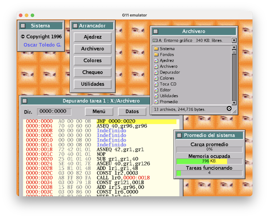
Once upon a time in the mysterious lands of Mexico, starting in Fall 1996 and through Spring 1997, I coded a windowed operating system in 32-bit machine code, fit it into a floppy, and jumped in excitement as it boot up.
Of course, I knew it was a great thing because you couldn't boot Windows 3.1 or GEM from a floppy disk, but I was very far from knowing how so cool it was. Unfortunately, not a thing I could give away for everyone to see, as it was written for a homebrew computer based on the Am29000 processor.
Let’s go back to my memories, some notes, and the ride of discovering again what I forgotten.
The world's fastest processor
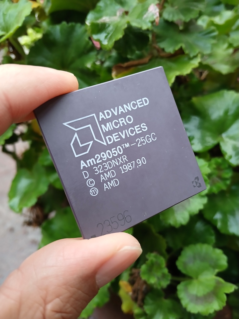
If you've been following my series of articles on transputer, I was feeling very satisfied with my operating system, and I had reached the limits of the system. My father on the other side was busy developing a new computer system based on a new 32-bit processor. Well, in 1994 it was only new for us. The AMD Am29000 processor came out in 1987, also announced as the world's fastest processor (do you see a meme here?) and it could process one instruction every cycle, so indeed it was fast.
The Am29000 processor and its successor the Am29050, were used in several Postscript language add-ons for printers, video NuBus cards for Quadra Macs, arcade games like F-15 Strike Eagle and Battle of the Solar System (both by Microprose), and I read in the Wikipedia it is also inside avionics in dual-processor boards for redundancy.
These processors have a Harvard architecture (instruction and data memories are separated), 64 global registers plus the register stack pointer, and 128 local registers using a register window (similar to SPARC and Intel i960). The register window is basically a stack cache for faster access.
The speed was based on a ton of assumptions, like having fast enough RAM or ROM, or having very high-speed TTL chips. And all three were still very expensive in the early 1990s. Besides some bus design decisions for the Am29k family like a separate data and instruction bus made it really cumbersome to interface it. At the end, doing anything useful with the Am29k required DRAM memory, and it was slow, and then all the advantage was lost.
However, my father was confident in static RAM memory and he sourced dozens of 128KB static RAM chips with 8-bit bus. Surface mount started to making an appearance and several of these were built with four 32K RAM chips mounted in nice miniature green boards.
So the first Am29000 computer made by my father ran at 6 mhz, and it had the whooping memory capacity of 512 KB of RAM, along 128 KB of EPROM (using two 16-bit chips). It had ISA connectors, and the video was a Cirrus Logic GD5429 card, along a standard parallel/serial/floppy-disk controller card (multiport card), and reused the keyboard chip from an old PC to interface AT keyboards. This computer was called G11.
It was a team work, he did some initial programming to start the processor, I translated my Z280 code for initializing the Cirrus Logic VGA, made the keyboard decoder, and the disk routines. Once this was stable, I went ahead to work in the monitor program for listing the memory, saving data, and as the instruction set was complicated enough, I also integrated a micro-disassembler and a micro-assembler. This means we could code with real mnemonics, although no labels could be used, also moving code was a complete pain.
We needed to return to the Z280 machine to program the EPROMs, but everything was going really well. I stumbled in the dark reality that I needed to port everything from the Z280 machine to this machine, it was like 200 programs between applications, utilities, and games. Besides the Z280 programs were basically outdated, I couldn't replicate the same.
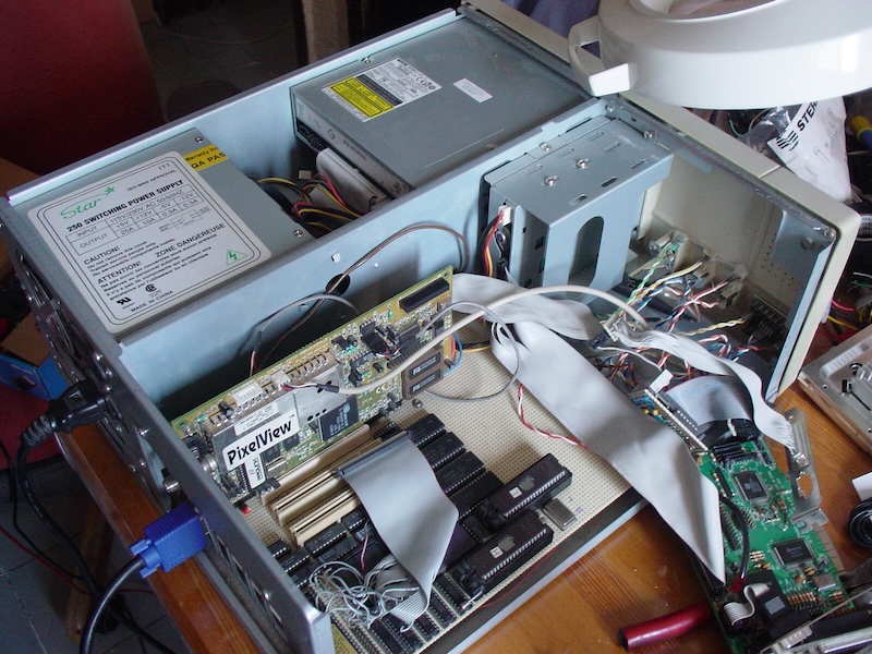
I wanted a G11V1 picture, but there were no digital cameras before 1999 and I don't know where is the machine. So this is a picture of a G11V2 computer, you can see four 512KBx8 memories and it has already PCI bus (not present in the G11V1).
Intermission
As the G11 computer was finished, my father took over it and started to investigate how every processor special register worked or why it had certain values, and writing documentation about it. I was somewhat startled, because I believed the processor was already documented in its databook, and I wasn't interested in undocumented behavior, but anyway, I ended typing all his notes and printing them.
I could concentrate on the transputer now that it was available for my use, and I switched ocasionally to the G11 computer when it was free in order to enhance the floppy disk operating system, I started coding some games, a text editor that handled our new Canon BJC-600 bubblejet printer, and even a MSX emulator. This was the first time I could see Gradius running, I was hooked.
I was recreating my Z280 programs, and I felt like I was going backwards when I had already an advanced operating system in the transputer. In the meanwhile, Windows 3.1 looked more useful with all its icons in shrill colors, a product of the palette inherited all the way from CGA.
I was interested in discovering how to do a windows system, but I couldn't get my hands on a programming book for Windows 3.1. Local libraries were still filled with tons of Turbo-C, Turbo-Pascal, Quick-BASIC, and QBasic books. Finally, I got a discount book about OS/2 programming, and I started to read it. The author did an excellent work introducing OS/2, and it was easy: open a window, draw in the window, close the window.
The real discovery was... *badum-tss* the message pipeline. Every process with windows has a message pipeline, and when you create a window you should assign it a kind of interface handler (the window class), and this handler reads the messages and it does operations according to the user’s interactions.
The user’s interactions are simple for starters, a message indicating a click from the mouse, a message for moving the mouse over the window, and then things start to get complicated with double-click messages. You can create windows inside windows, but these are controls like buttons, slide bars, icons, indicators, status bars, etc. And these controls can send messages back.
The beauty of this is that you could develop user interfaces very fast, and every single program looks great (well, in the 90s we weren't really too exigent, as Digital Research’s GEM can testify)
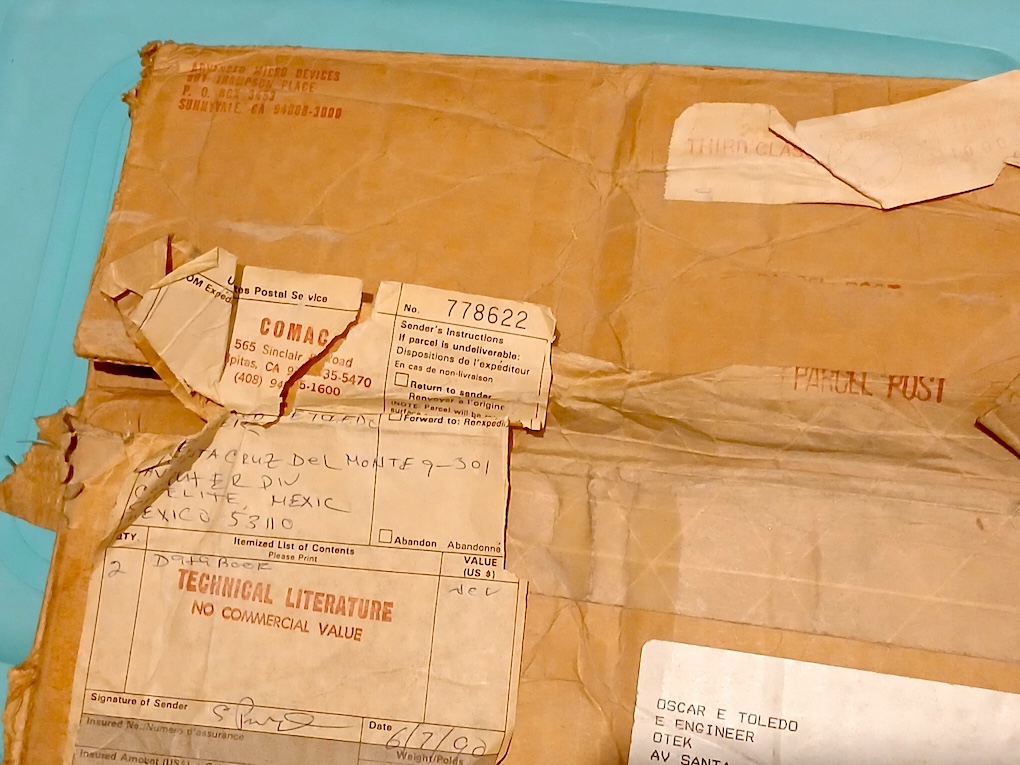
While researching for this article, I discovered I still had a box where AMD shipped two databooks. Someone dropped it at post office in June 7, 1990.
The windows system
First, I needed multitasking. I found this daunting and complicated, and I ended learning how to do cooperative multitasking. It saved the current state, loaded the new state, and jumped to the new place. Sorry, operating system designers, I didn't think about it. I just wanted it to work.
Second, I needed windows. I scratched my head really hard thinking how to overlay things one over another. Then while I was reading file after file of a new CD-ROM bought by my father, I discovered X11R5. In case you didn't know, X11 is a networked windowing system designed to work with almost any graphic terminal, and as universities had a lot of different hardware, it should work on all of them. Of course, this means it was extremely clumsy for handling color or games.
The important thing here is that the CD had the complete source code for X11R5. Of course, I couldn't find any use for it as my computer didn't had a network, nor a C compiler, but instead a single source code file was enlightening: XRegion.c.
The algorithm's basic concept is that every single window has a rectangle display list. If a window isn't overlapped then the rectangle covers the whole window. If a window is overlapped, cut the overlapped rectangle, and continue cutting every overlap. This means that if a rectangle is cut in the center, it creates four rectangles, and for displaying information, you should try drawing in the four rectangles. So a heavily clipped window is slowly drawn. By the way, Apple has a trick for this, it uses a clipping bitmap, but it is a patented technique.
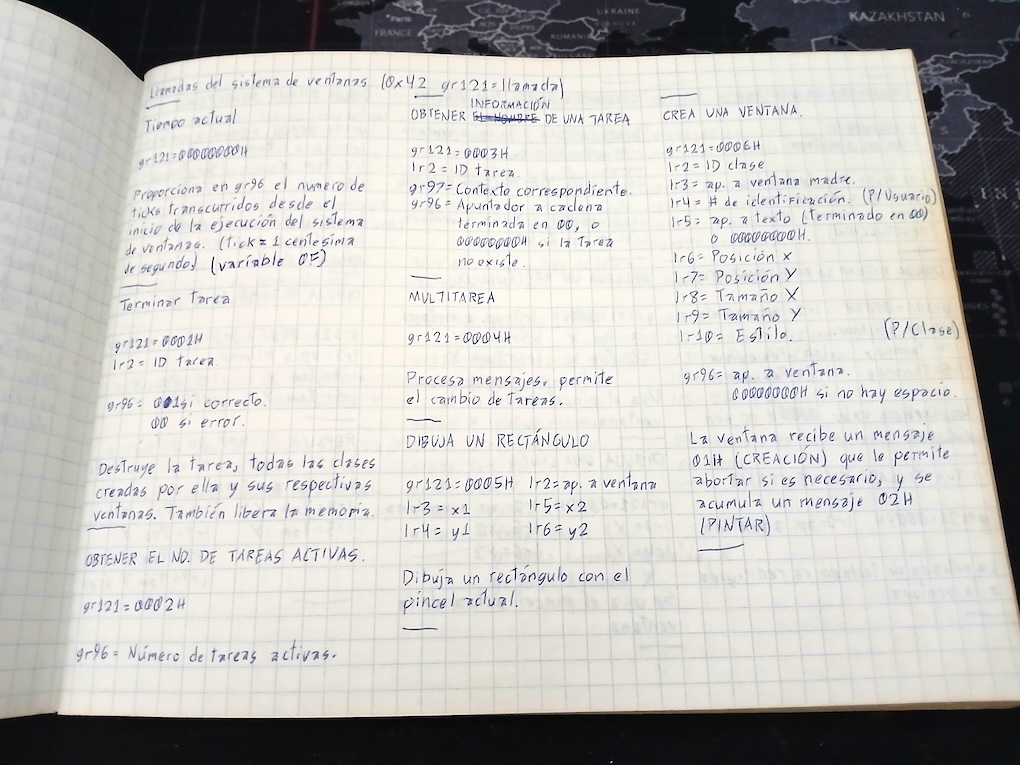
Third, I created an extremely simplified API specification in my notebook based on what I learned from the OS/2 book, and this made coding a lot easier. While OS/2 (and Windows 3.1) use a graphical context for drawing with pen types and fill patterns, I considered this too cumbersome, and you draw directly in the window in pixel units.
Specifications of the first few functions of my windowing system.
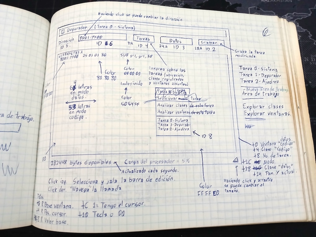
User interface design for the debugger (Depurador)
With these three pieces I started coding my windowing system in machine code starting in Fall 1996 thru Spring 1997, I was age 18, and I really never thought that my micro-assembler worked against me. It was easy to use, and I could code routines very fast, and then my micro-disassembler showed me exactly the same I wrote. I just needed to write some pointers in paper, but unfortunately this wasn't exactly source code.
This article is possible because I have two disks with the early machine code version from 1997. I know I had something good, even if primitive, as no other windowed operating system boot up from a floppy disk, but it is impossible someone else could experience it without an Am29000 computer. So let’s code an emulator!
The 1997 disks
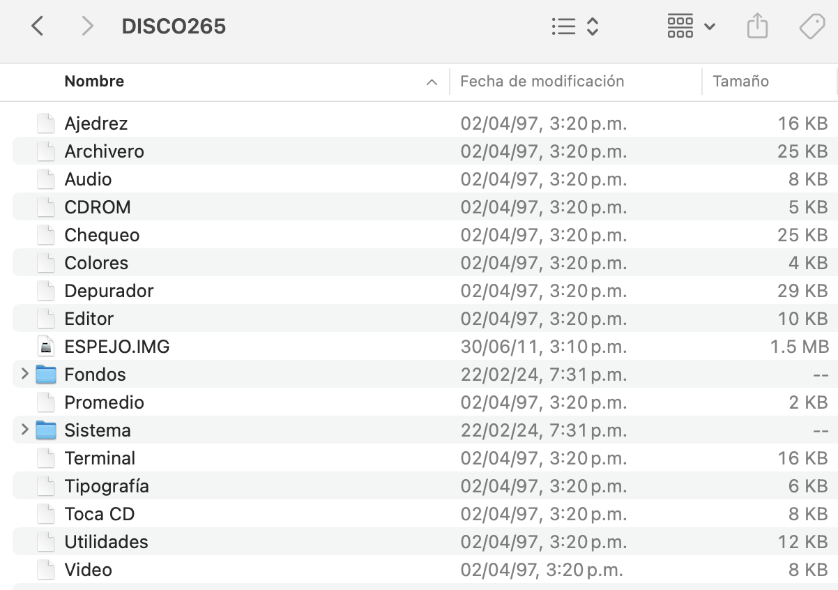
The main directory of the bootable disk looks like this:
The directory of the bootable disk. The ESPEJO.IMG is the dump, and the folders have the date of the restore.
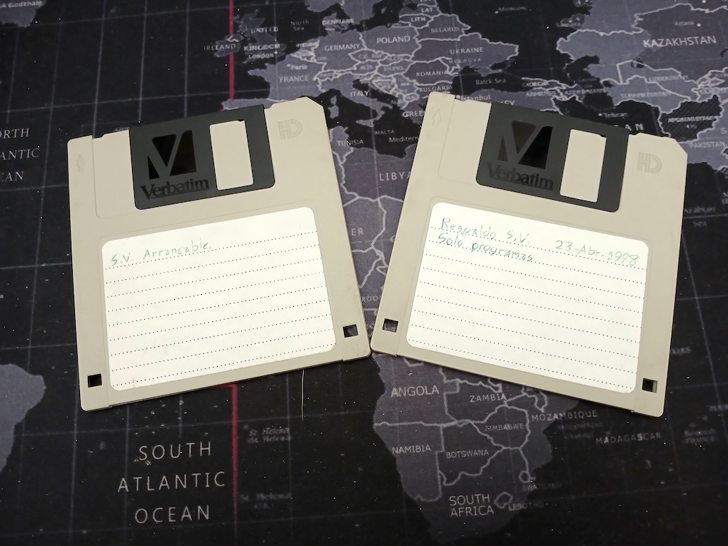
Two floppy disks of 1.44mb capacity with my windowed operating system and programs.
My first task was writing an Am29000 emulator. I have the user's manual somewhere, but instead of losing time searching for it, I lost time searching for it in Google, and nothing available. I was surprised, because it was available a few years ago, anyway, I went to archive.org and I got it pretty easily after typing the chip number.
I consider the relational-assert instructions the biggest waste of silicon space in the Am29k series of processors. I suppose the designers had a use case because the military required the Ada language, but I'm just speculating.
Another curious idea is the result value for the comparison operators, a boolean value of 0 and 0x80000000, and the conditional jumps check only the high-bit to jump, so you need to do a 31-bit shift to the right in order to get the C language boolean value.
The addition and subtraction instructions also come with extra baggage. In this case, the processor generates a trap if the result exceeds an unsigned value, or a signed value. This means there is ADD, and also ADDU, and ADDS. If we consider the carry flag, it increases to another 3 instructions: ADDC, ADDCU, and ADDCS.
The subtraction instruction has a set with reversed operands, so we have SUB, SUBU, SUBS, SUBC, SUBCU, SUBCS, but also SUBR, SUBRU, SUBRS, SUBRC, SUBRCU, SUBRCS. Maybe I'm not too smart to see how to use SUBRCU.
Where is everything?
I used to believe I could remember everything, but apparently my brain disagrees. I've these two floppy images, but where is it loaded? Fortunately, I put a boot message saying "Arrancando", and the code pointing to this message are these two instructions:
CONST gr68,0x0180
CONSTH gr68,0xbfff
This means the boot data should be loaded at 0xbfff0000. It doesn't means I had so much memory (the RAM starts at 0x80000000), it just used the mirroring feature of the RAM decoder to always put the boot code in the higher 64KB of RAM. Also I could see by the byte-order of instructions that all of the code was big-endian. The Am29000 processor allows to choose the endianness with a bit in the configuration register.
With the emulator in development, I started running it with the disk image. To my dismay, I discovered I made a nice boot screen that required ROM routines that I don't have at hand (handling box drawing, icon display, disk reading, and the preliminary setup of processor registers), so I made a patch to jump over these, and the loader ran complete until it jumped into the void at 0x80000000, as nothing had been loaded.
I made a phantom ROM that reads the disk using a special instruction coded in the emulator, and returns on unhandled services.
The incomplete emulator behaved really well and it loaded the initial code for my windows system, and then it stopped with an unhandled instruction 0xe2. I was mystified because no instruction was shown in the Am29000 User’s Manual, until I got the Am29050 one. Silly me! It is the MULTIPLU instruction.
The Am29000 manual is obsolete in the definition of trapped instructions. When AMD created the Am29050 with floating-point support and hardware multiplication instructions, they redefined the trapped instruction set. For example, the opcode 0xe4 is CVINTF in the Am29000 User’s Manual, but it is CONVERT in the Am29050 manual, and AMD provided a math emulation library to allow Am29000 processors to run Am29050 software using these new opcodes. I considered it was overkill to write an Am29050 emulation (maybe later), so I limited myself to Am29000 because I find fun how they implement the multiplication instruction using a trap and 32 continuous MUL instructions (bit-shifting all the way).
By the way, we got our Am29050 processors as samples directly from the Mexico representative for AMD. I took note of the date in my notebook, April, 8, 1997. Unfortunately, the same year that AMD was struggling, and dropped the AM29k line in order to make the K5 processor, and this way the processor war with Intel started.
After a brief disagreement with my interpretation of the vector table, I finally managed to get the MULTIPLU instruction to trigger a trap for emulation, and I ran to implement the MUL instruction, just to get an infinite loop of multiplication traps. It happens that in order to return from a trap, you must rebuild two PC registers!!! Updating just one of these made my code to rerun itself again, and also the trap set the wrong return address.
I had to correct these bugs, and when running the emulator again, it exit the multiplication routine directly to an overflow trap *clown face* And indeed there was an overflow, because it was reading memory that I don't remember what contained when booting the machine. I put some guessed values until it reached the IRET instruction, meaning it could return from the emulated instruction.
It worked, and then stopped on the unimplemented DIV instructions. I certainly had my doubts about the instruction bit process, but I implemented the algorithm as described in the manual.
I reached a point of the original code where it started reading bytes from memory further requiring another bit to implement (to set the internal byte pointer), along the EXBYTE, EXHW, and EXHWS instructions to extract bytes, unsigned half-words, and signed half-words.
Soon came the INBYTE and INHW instructions, and also were implemented.
What is this?
For some reason I read a port 0x90 deep into the system initialization. Worst, it waits for the bit 7 to turn on... I don't know what is it! I just put a 0x80 byte for that exact port. BTW, reading ports uses a special LOAD control 0x41. The normal ones for memory are 0x04 and 0x14 (for bytes or half-words).
Excellent! It got stuck in a loop checking a register that never changes, except that obviously it should change, but it could only happen if interrupts are processed. Of course! I forgot completely there is a time reference for context switching, the internal Timer register of the Am29000 processor. This in turn could give light on the early use of MULTIPLU and DIVIDU instructions, probably getting the timer value to load.
I added a code to trap access to the timer registers, and I got this:
I had to write a routine to dump the half-megabyte RAM so I could examine it. It happens the computer speed was hard-coded into the operating system, 6000000 or 6 mhz. So where the value gets lost? I went in a debug spree for around three hours!
It wasn't a mistake in the routine, instead it was a bad macro invocation in my emulator. I used RA instead of REG_A, and the macro was valid but gave wrong data. I renamed that evil macro to _RA to avoid mistakes in the future.
Let's code interrupts!
The timer is decremented in each processor cycle, so it is easy to implement as most instructions are one cycle long, with the exception of traps, and LOADM and STOREM instructions.
I implemented the counter reload, and made it to create an interrupt. Ran again the emulation, watched how it entered the first loop, and it exit correctly when the timer counted. Now it entered a different loop trying to read the port 0xfd0. Remember, this was connected to an ISA bus, but there wasn't an easy way of decoding the lower two bit addresses, instead my father wired processor A2 to ISA A0, and this went successively. So 0x0fd0 / 4 = 0x03f4, the port for the disk controller.
Up to this point, the disassembly generated by my debugger missed some information, so I added the addresses for the jumps, and the ASEQ instructions with identical registers as operands were replaced with NOP mnemonics, as this is the way to create a NOP instruction.
After stopping the debug in the first access to floppy disk, I discovered it was very simple. It was trying to turn on the disk motor, and that's the cause it was checking the interruption count in gr82, in order to spindle the motor.
I wasn't going to write a Floppy Disk Controller chip emulation (although I was close because I searched for the NEC 765 datasheet), but patched it to call the emulator directly.
So far two days writing and debugging 1500 lines of source code.
The obsolete floppy
Trivia time. Do you recognize the following command numbers in the CPEQ instructions?
This hand-coded assembler routine handles the floppy drive unit. Instead of accessing it directly, it is abstracted so the operating system handles all drives with the same interface, and these are SCSI commands.
0x1a - Mode Sense.
0x25 - Read Capacity.
0x12 - Inquiry.
0x00 - Test Ready.
0x03 - Request Sense.
0x28 - Read 10.
0x2a - Write 10.
Notice how the routine returns two status values at the same time. A thing you can do easily in assembler, but not possible with the C language.
This software elephant is built from several machine code modules. One of these is the floppy disk controller, disguising as SCSI unit -2 (that's right, negative 2) because units 0 to 7 are for real SCSI drives, all the way inherited from my transputer operating system. And in turn the ports 0x90 and 0x94 were connected to a Western Digital WD33C93 SCSI controller, I’m wondering what happened with these hard drives.
Notice also the extra instruction after JMPI lr0 it is a delay-slot instruction. Every jump or call in the Am29000 processor has this space for an instruction that is executed before doing the branch.
Sunday morning
After coding a SCSI emulation for the floppy disk, patterned loosely on the machine code, I ran again the emulator expecting it to start reading the following files for completing the boot pattern, but instead it only checked the floppy disk capacity and crashed silently somewhere.
It is way easier when it triggers an undefined instruction, but it ran in circles around the crash. Going thru the debug log I discovered it expected a 0x42 value from the port 0x94, so I gave it, and the execution advanced again and crashed.
This time it initialized the serial ports!!! In case you don't remember we used to have COM1 to COM4 located at I/O addresses 0x03f8, 0x2f8, 0x3e8, and 0x2e8 respectively. Once I implemented a stub, a crash happened when trying to access the drive to load a file. I tracked the file name to the address 0x8000bd20. This is the mirrored dump:
It says "X:/Sistema/Controladores/Video/CL-GD5429 800x600x64k" as you can see each letter is half-word, very bold for a system with 512 KB of RAM, but then I was pretty sure Unicode was the future (yep, that was a good prediction!) This is the video controller name, and the Cirrus Logic GD5429 was a very popular VGA card then.
The X drive letter was my "magic" letter that was replaced by the boot drive. The problem was the start drive set to J (address 0xbffffbf0). I tracked it back to the start of the boot code and it read a location 0xbfffffdc without a valid value, I tested first zero, and the start drive changed to C. After some reverse engineering I saw the value 0x40 put the correct start drive A.
I had to add the LOADM and STOREM instructions as these handle the spilling of local registers to memory when the register stack is full, and the MULU, MULTM, and MULTMU instructions, these last two are traps.
The organization of registers is per the AMD recommendations, using the "global" global registers gr64-gr95, and for procedures the "local" global registers gr96-gr127. Furthermore, the stack frame is cached in registers lr0-lr127. Only big structures get into memory using gr125 as stack pointer, so you have dual stack pointers (gr1 and gr125).
The new debug log displayed the sequence of searching for the video controller:
It can be seen the jump is one word ahead of the right address, it is missing the SUB gr1,gr1 instruction. Immediately, I figured that the problem was reading from the PC1 register of the processor to get a relative address, for example MFSR gr96,PC1.
I discovered to my great horror that my PC registers were backwards, PC0 should have pointed to the next instruction, while PC1 should have pointed to the current instruction. Furthermore, the correction disrupted my trap handling code.
After going over it, I found a way to make it elegant and understandable. As this is a static processor, there is a non-described behavior of previous and after values for program counters. Now when decoding an instruction, it automatically reads the instruction from PC1, and saves the current PC0, PC1 and PC2 in the processors registers (the right values for returning from traps), and then the shadow PC counters change place so the shadow PC0 can get a new address for jumps (remember each jump has a delay slot).
The rewriting of the code allowed the emulation to load the video controller from the floppy disk, and go far than ever by trying to erase the video memory:
The special value 0x00 instructed the Am29000 to access the ISA memory bus (control value different from 0x04 for the internal memory, or 0x41 for the I/O ports). I'm so close to see something on the screen!
The human’s memory is blank
I had a small problem, I didn't remember how the video RAM memory was mapped! And I noticed immediately there were acceleration routines specific for the Cirrus Logic GD5429, in particular the hardware cursor. I never could knew I was making more difficult the work of my future myself!
This card in particular had 1 MB of video RAM (a real monster in the 90s!) allowing for 800x600 pixels in 16-bit color.
It could take me several days to write a small emulation of everything I needed! I tried looking for an emulation of Cirrus Logic GD5429, and I found qemu and pcem already handled that. Both are open source too, but the emulation code is incredibly dependent on several other structures required for easier and faster emulation. In particular, the include files call for other files totally unrelated, like the timing structure used in their emulators, or the PCI support that I didn’t required.
I tried a whole day to adapt one of these but I found the task was daunting and taking more than my available time. I could develop my own emulation for the handful of functions used by my operating system, so I went to download the CL-GD5429 Technical Reference Manual.
It shouldn’t be too complicated, taking any access to CRTC, Graphic Controller, Attribute Register, and Sequencer Registers, saving these in an array, and catching accesses for the video memory, cursor memory, and acceleration registers.
I made also a debug output of the video registers, and I had a blast of good memories reading again the technical manual (at the time I had it printed because PDF viewing was slow!) and I could determine the register where the 5-6-5 RGB mode was setup (value 0xe1)
Cirrus Logic made easy the access to video memory allowing to write eight pixels with a single byte write. This is because it expanded the write to take pixel data from the extended graphic controller registers, and also it could be masked so you could put a bitmapped letter without affecting the background.
However, it also allowed to change mappings in the fly to a planar memory where you could deposit 16-bit pixels directly into video RAM. As the RAM window is 128 KB wide, there is a banking register scheme.
And here is it. Changing write mode to 0x00 (graphics register 0x0b), calculating lr15 * 800 + lr14 (pixel address for 800x600), setup gr103 to point to video RAM at 0x0a0000, extracting 64K page in gr98 and writing graphics register 0x09 with the value shifted 4 places to cover the 1 MB address space.
Your processor is buggy
After the stub for the video chip was there, the execution could proceed. I got stuck at cycle one million with a conversion from float to double that crashed because the mantissa was non-zero. I decided to patch a flag to avoid the crash but not before using a whole day trying to find a way to setup the flag.
As the execution advanced, I could see there were a few further bugs in the MUL and MULL instructions. It happens the sign bit inserted in the result should be complemented in case of an overflow. I ran in circles for four hours, until I got right the overflow detection.
Once all instructions were right, the execution ran without stopping, and this means the operating system was up and running. Now I needed to see what was appearing on the screen, but the machine “mind” was thinking different.
Suddenly, the execution stopped at 295,433 cycles with an invalid instruction. As the emulator behavior is deterministic, something was changing, and I noticed some write disk commands were issued. I did a comparison of the original disk image and the newest one, and it overwrote the File Allocation Table, so any future file access was bringing trash and crash.
Now I only had to revise around four million instructions executed trying to find what brought the operating system to write in the wrong place.
Tracking the bug
The bug happened through a perfect storm. The disk image had three temporary files that were deleted at the start of the operating system. However, somehow along it corrupted the disk image.
At a first glance (or through 12 hours of effort reading the debug file, drinking lots of coffee, and trying to make sense of the RAM dump) I thought the FAT update was buggy, but after following the logic of file creation, I discovered the search for the free block gave the wrong number, as it tried to write the first block of the file into the block 1 (casually the same block as the FAT)
The first time it wrote data into the file, it searched for a free block. Unfortunately, the routine 0x8000f20c for getting the first free block was simply gr96 = drive[0x70 / 4] this means the value was precalculated.
This made me to return to the very first cycles setting up the drive for reading (204575 cycles into execution), where it reads the complete FAT to get the total number of free blocks. At 0x8000e7f0 it sets the counter into lr5, and lr7 to zero (free blocks). The loop itself is 0x8000e7f8 (subroutine 0x8000e864 reads the FAT table).
If the CPEQ instruction result is true, it shifts the true value (0x80000000) 31 bits to the right, and adds it to the lr7 register. If it finds a free block, it checks if it is the first time, and saves the block number (for creating files later).
The total number of free blocks is saved into the drive structure lr18+0x6c and the first free block into lr18+0x70, and... this routine saved correctly the block number.
However, I had now a fixed address (0x80022cb0) that I could watch for the wrong value. I discovered it was being written not only with 1 but also with -1 and 2. This was a big error.
Watching address 0x80022cb0 now written with 0x00000123
Watching address 0x80022cb0 now written with 0x00000001
Watching address 0x80022cb0 now written with 0xffffffff
Watching address 0x80022cb0 now written with 0x00000001
Watching address 0x80022cb0 now written with 0xffffffff
Watching address 0x80022cb0 now written with 0x00000001
Watching address 0x80022cb0 now written with 0xffffffff
Watching address 0x80022cb0 now written with 0x00000001
Watching address 0x80022cb0 now written with 0x00000002
Stopping it at the point where it was written with 1, I discovered it was the FAT writing routine, and it worked correctly to free a block, and in turn changing the first free block to the lesser number. The problem was the caller.
The base caller was the file deletion operation called at 0x8000c7b8. The file to be deleted was X:/Sistema/Temporal/00000001.tmp with block 0x0123, correctly annotated in the FAT as linking to 0x124, and then -1 for finishing the chain.
And then I found the culprit, the instruction EXHWS, extract half-word with sign:
                if (d >= 0x8000)
                    d = 0x10000 - d;
Can you see the bug? This piece of code should translate the 16-bit value into a sign-extended 32-bit value. Instead you get the absolute value. When it got the end of a FAT chain, it returned 1 instead of -1, and this mistake caused it to write zero in the entry 1 (the FAT block).
The correct routine is:
                if (d >= 0x8000)
                    d -= 0x10000;
Yes, a single line mistake took me three complete days of debugging. And of course, you can make this bug in any language.
Now the FAT wasn’t destroyed, and I could get back to find why it still crashed.
48071124 cycles!
The following crash only took me four hours to solve. The MULTIPLY instruction was crashing with big input values. However, I noticed the trap was disabled for an Am29050 processor, but this flag wasn't transferred to the math emulation, and it crashed on overflow.
I replaced the gr95 content with 0x00040040 (it was already 0x00040000 for the CONVERT flag) and et voila! The emulation run up to 48 millions cycles and stood running in an infinite loop. I was waiting for something to happen, but instead I got a warning of lack space from my MacBook Air, as the debugging file was running at more than 150 gigabytes, filling very fast the SSD.
Ok, but what was doing the operating system in boot? I discovered my operating system didn’t included bitmapped fonts, but instead it was creating three fonts on-the-fly for the system. As I said before, I learned how to draw windows from X-Window, but also I discovered the Type 1 rasterizer with MIT license.
In the good old days, you were limited by the fonts provided by your laser printer. It could be Courier 12 points, in bold, and italic. And if you required more fonts, you would bought ROM cartridges with fonts! Lucky people could buy a Postscript cartridge and get unlimited scalable fonts! And by the way, there was a very good chance your Postscript had an Am29050 on board.
But I wasn’t so lucky, instead I discovered Type 1 was the font format used by Postscript. X-Window also provided some basic fonts. The X-Window fonts weren’t hinted so nicely as the Adobe fonts, I got mine from an early version of Acrobat Reader.
So guess what I did? I didn't had a C compiler available yet, so my port of the Type 1 rasterizer was a manual conversion of the C source code to machine code. I don’t remember how much time it took me, but I should have somewhere an annotated print of the source code with machine code addresses.
Time to say that I don’t know how I had so much energy to do these machine code programs and manual ports!
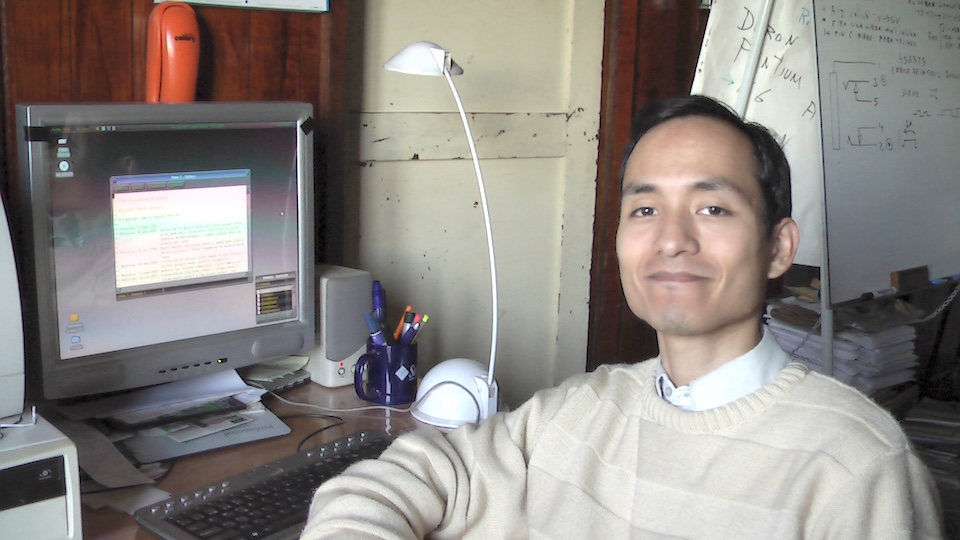
Myself in 2007 along an advanced version of my operating system in the screen
libSDL2, nice to see you!
Now the cursor should be in screen, even if I cannot see it. The only problem is that I didn’t have written yet the acceleration routines nor a way to put the video RAM on the screen.
It took me like the whole day to find why Xcode wasn’t linking libSDL2 to the project. Hint: It isn't in the project options. I finally discovered you should simply drag&drop the SDL2.framework folder to your frameworks in the project tree. A few hours later, and after discovering I was missing a call SDL_UpdateWindowSurface(window) to update the window, I got meaningful trash on the screen!
This gave me a sudden adrenaline boost and I proceeded to correct my GD5429 emulation to copy correctly expanded bitmaps (letters became legible), then the minimum required bitblt function to fill the background with the wallpaper, and finally the same bitblt function for 8x8 pattern copy so it could fill windows backgrounds. It was a complete shock for me! I didn’t remember how it looked!!! Besides I was sleepy because I was doing this at 1am in the night!
The Cirrus Logic GD5429 limited emulation is coded in only 500 lines of C language, pretty small and readable.
For the input, I remembered I used a serial mouse working at 1200 baud rate. I searched my machine code for a register being set to 1200, because it has a serial driver library that converted this to the 16550 clock frequency. The subroutine to setup the mouse is located at 0x80011800. Did you know that the mouse sent back a letter telling you the protocol? You could get a M for Microsoft protocol, or H for the Mouse Systems protocol. After decoding the bytes received through the serial port you would get the registers gr92 and gr91 with the mouse position.
I could go the full way to emulate an asynchronous serial chip, along a mouse, but instead I resorted to receive the SDL events and change directly the same registers that my code did. The X-coordinate is in gr92, the Y-coordinate is in gr91, and the buttons state is saved into gr90 (bit 2 = left button, bit 1 = middle button, bit 0 = right button) We used to have three-button mouses before it was common to see gaming mouses with 6 or 8 buttons.
The key buffer start and ending locations is determined by 0xbffffa00 and 0xbffffa04. While 0xbffffa08 is the writer (where the interrupt puts the next data), and 0xbffffa0c is the reader (from where the data is consumed).
Fortunately, libSDL2 provides an UTF-8 text input that I could process, and I used exactly the same locations to put Unicode keys, and patched the keyboard controller to avoid the scancode decoding and pass directly the Unicode characters to the operating system.
For the final polish, I wanted to see my original cursor sprite. It wasn’t so difficult this time, I made code to draw the cursor directly in the video RAM, and save/restore the background before displaying on the screen.
At the end, the emulator is composed of 3075 lines of source code coded in two weeks.
Creating a distro
It would be really easy to publish the two floppy disks exactly like in my files. Unfortunately, these disks were reused several times, contain unknown trash in unused sectors, and several programs were buggy and in various states of completion.
First, I needed to replace the non-free Adobe fonts with free Type 1 fonts. For this, I created a build_disk.c utility (it is in my git, like the one for my transputer operating system) to create a floppy disk image, then I patched the operating system to allow for two floppy disk drives at the same time, and I was able to copy the new fonts (Luxi family) simply by dragging and dropping them. I patched manually the operating system for the new fonts, and bingo! It worked just fine.
Second, I had a HP LaserJet II printer driver, but I copied two extra printer drivers (Canon BJC-600 and Epson Stylus 600) from my second floppy disk, and added support for printing in the emulator. This means that if you actually have one of these printers, you could print text edited with the Editor program! I was able to view a printed file for HP LasertJet IIp using https://www.coolutils.com/online/PCLViewer
Third, I made a program to “clean” the floppy disk image, by erasing unused blocks, and removing data at the end of files (sanitize.c in my git)
So here it is. My operating system for Am29000 processor written entirely in machine code. A once-in-a-lifetime achievement.
By the way, it has a name, very deep inside the binary image it says Windows Fénix. Someone asked for the name of the operating system, and I had been watching X-Men’97 at the time, my preferred character was Jean Grey (Phoenix), so that’s it.
Download
You can get the emulator from https://github.com/nanochess/Am29000 and there are precompiled releases for Windows and macOS. Maybe you will need to install libSDL2.
When the blue window appears, you should just drag&drop the floppy disk image disk.img into it. If you drag a second floppy disk image, it will be used as drive B.
If you print something, the printer.txt file will appear in your Documents folder. When printing the cursor will move more slowly because the printer task works in the background, just make sure you don't close the Editor window until the cursor move fast again. You need to close the emulator in order to use the printer file.
What we have here
Move your cursor with the mouse or pad. Press click and keep pressed on the title bars to move windows. The gray button at the top-left will close the windows.
If you do right-click in the background of the “Arrancador” window, you’ll get different color schemes.
The “Arrancador” window is like a shortcut launcher for a chess game, the file viewer (you can drag&drop files between two file viewer windows), color editing, disk check, and utilities (you can drag&drop files to the trash, or drag a folder to create a new folder in the file viewer)
Colores: A way to edit the operating system colors.
Depurador. A bare bones debugger that can disassemble global memory and the current tasks. You can click the disassembly, and type Am29000 assembler mnemonics (press Enter at the end)
Editor. Text editor that can print documents (very glitchy)
Promedio. Procesor usage and free memory.
Tipografía: A way to test font faces and change used ones.
CDROM: This enables a ISO-9660 file system, but there’s no CD support in the emulator.
Terminal: A serial terminal, but there’s no serial port support.
Circuito impreso: A demo of vectorial graphics.
The folder Fondos contains background pictures, just click one to enable it.
The folder Sistema/Protectores de pantalla contains a single screensaver called Acuario, but no time check to run it. The graphics are based on XFishtank.
Some internals
How my operating system works? It starts by initializing the processor state, sets the math emulation package, calls the initialization routines for each service provided, erases the temporary files from disk, loads the video controller, and then builds three font faces for the system. The services are invoked loading the function number into gr121, and doing CALL to a single instruction ASNEQ 0x42,gr1,gr1. There are services 0x42-0x4f.
0x42 - Windowing system.
0x43 - Video controller.
0x44 - Keyboard controller.
0x45 - Memory management.
0x46 - SCSI controller.
0x47 - Serial port controller.
0x48 - Filesystem interface.
0x49 - Mouse controller.
0x4a - Font manager.
0x4b - Message boxes.
0x4c - Multimedia services (not available in this iteration)
0x4d - Configuration services.
0x4e - Printer services.
0x4f - Network services (not available in this iteration)
Of course, this is completely tied to the Am29k architecture.
I think I got the math emulation package from an Am29000 binary that I got somewhere in Internet. The stack handling routines for local registers came from the processor user’s manual (ASGEU 0x40 and ASLEU 0x41) Vectors 0x00-0x3f are for internal processor traps and emulation instructions.
I've provided also a full disassembly and RAM dump in my git for reference purposes. Maybe I could document it in the future.
Did you enjoy this article? Fuel my creativity with a coffee ☕. Or join the journey and become a monthly supporter, you’ll get high-quality content, and good karma! You can buy also my books in Lulu.com, my ebooks and games in my digital store.
Postmortem
I learned my lesson. This was the last time I did something so big in machine code. The programs required way too much documentation and commenting addresses, and every change was a pain. Sometimes enhancements or corrections didn’t fit in the same space, slowly making the operating system an ever bigger chaos. The text editor in particular never could be corrected because it was too complex. However, coming from doing the same on the Z280 computer, it was pretty hard to avoid old ways.
While writing the emulator and this article, I noticed that the date was fixed on the whole operating system, so all files are dated 1997, even though some internal copyright messages are dated 1998, and one of the floppy disks says 1998 in the label. Based on this data, and my notebook, I developed this between late 1996 and early 1998.
In 1997 I would change the endianness to little-endian for the G11V2, and put the whole operating system in EPROM (it had 1 MB. of EPROM memory) allowing for bigger programs to run.
It was until December 1997 when I finally started porting the C compiler from my transputer operating system, it was working in June 1998, and it helped me to code faster. It was instrumental to create my first Internet browser in 1999 in the G11V2 computer, but of course, it would be for another articleit is in the next article.
I remember downloading QNX in 1999 and running it in a 1.44mb floppy disk on a PC, and thinking "Gosh! I did it first."